Greetings one and all!
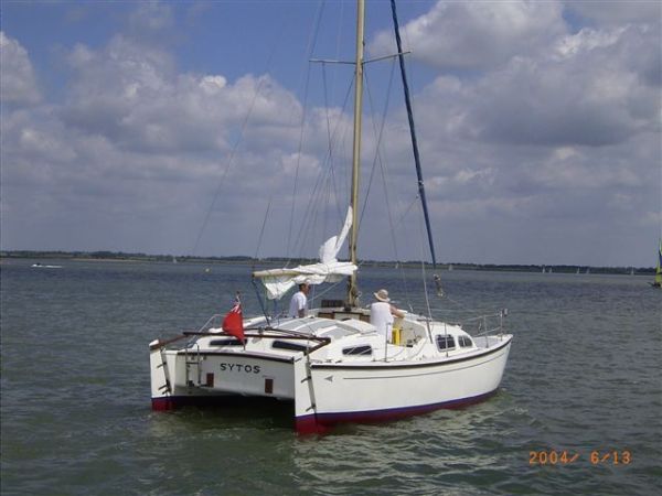
Wow what a great forum. I just discovered is a few weeks ago and have been busy reading. Hope I can join your crowd. I sail what I consider as a plastic classic, a 1977 Heavenly Twins 26. Probably more than a few of you are scratching your heads having never heard of such a boat. Well she is a Pat Patterson designed catamaran. I believe her distinction is being the smallest plastic cat to cross oceans and circumnavigate. I think I will feel more at home here since the typical mult-hull forums only want to talk about their half million dollar wondrous 40ft
I’m hoping that some one might give me some guidance of a few topics. First I’m looking for a way to stiffen up the forestay. The current design is twin stays down to a wire bridle about 1.5ft off the deck connected to the hulls. Very slack. I’m thinking about laying up a kevlar tube for a cross bar, aka gull striker, with the center being the new attachment point. I’m thinking kevlar since not only would the stiffness be greatly enhanced it would also shave about 50lbs off the bow. Any comments or ideas?
Second I have a split back stay from the mast head. I’m thinking of using a slip back stay adjuster with a line run down to block/tackle with control run to the cockpit. Cockpit being in the center of the boat. Again any thoughts on this idea?
Please all keep your websites up, they make for great reading.
Ed
New Member, Kevlar, rigging Questions
-
Ed
- Bottom Paint Application Technician
- Posts: 16
- Joined: Sat Feb 23, 2008 5:35 pm
- Boat Name: Phoenix
- Boat Type: Pearson Triton 28
- Contact:
New Member, Kevlar, rigging Questions
Edward
S/V Phoenix, Triton #190
Wayfarer 16 Green Side Up
S/V Phoenix, Triton #190
Wayfarer 16 Green Side Up

-
Ed
- Bottom Paint Application Technician
- Posts: 16
- Joined: Sat Feb 23, 2008 5:35 pm
- Boat Name: Phoenix
- Boat Type: Pearson Triton 28
- Contact:
Yep, same type but no roller, she can't point too good as it is:)
I'm not sure how to embed a image so here is a link to what my rig looks like. All that teak is pretty but very heavy and not so strong.
http://www.3ddev.com/Tschuss/Logs%20200 ... leston.JPG
I just found a better pic of the rig here
http://www.3ddev.com/Tschuss/images/Snow.jpg
Where the sail bag is hanging is where the current bridle meets the foretays
Ed
Edward
S/V Phoenix, Triton #190
Wayfarer 16 Green Side Up
S/V Phoenix, Triton #190
Wayfarer 16 Green Side Up
-
LazyGuy
- Candidate for Boat-Obsession Medal
- Posts: 349
- Joined: Mon Jun 11, 2007 9:31 pm
- Boat Name: Paper Moon
- Boat Type: Luders 33 (Allied Boat Co.)
- Location: Mystic CT
That certainly is a challenge. On our monohulls to tighten the forestay, we simply tighten the back stay and it works because both are solidly attached to the hull. With your double head stay on a bridle the more you tighten the forestay, the more you are pulling the two hulls together. I am not sure that is a good answer. In my humble opinion your best bet would be to add a cross piece from bow to bow and a steel/spectra bridle between the existing attachment points to one attachment point for one forestay.
As for the backstay, the standard hardware for tensioning a split backstay will probably work. Take a look at riggingonly.com and look up backstay adjusters on the bottom of the page is what I am talking about. But with your present arrangement I would do something with the forestay before gaining all that leverage to pull the two bows together.
As for the backstay, the standard hardware for tensioning a split backstay will probably work. Take a look at riggingonly.com and look up backstay adjusters on the bottom of the page is what I am talking about. But with your present arrangement I would do something with the forestay before gaining all that leverage to pull the two bows together.
Cheers
Dennis
Luders 33 "Paper Moon" Hull No 16
Life is too short to own an ugly boat.
Dennis
Luders 33 "Paper Moon" Hull No 16
Life is too short to own an ugly boat.
-
suntreader
- Rough Carpentry Apprentice
- Posts: 59
- Joined: Wed Feb 07, 2007 2:26 pm
- Location: Gainesville, Fl
I've always really liked those first generation British multihulls, the Heavenly Twins is one of the most numerous. As I remember production moved from Britain to somewhere in South or Central America for the last quarter or so of the production run.
My first question is why do you think you need more forestay tension? There's probably a couple of good reasons, I'm just curious what made you think it was important.
A forward cross member on a cat has a lot nice things going for it You can get more tension on nets between the hulls with a forward beam to attach to, you can hang some anchor rollers over it, it adds another structural member forward while may or may not be a good thing. Incidentally, a 'gullstiker' is a vertical stanchion at the center of a cross beam with a stay running from the attachment points of the crossmember on each hull. 'Gullstriker' is a play on a dolphin striker which serves the same purpose (but pointing downward) on a bowsprit.
If you want to experiment with a crossmember the easiest way would probably be to built a beam of wood ala Warram cats and lash it to the bows. A more permament arrangement (but still affordable) would be to find a spar section or even an old mast you can cut down as the beam. One advantage of using a mast section is you can get them with the groove for a bolt rope making netting attachment easy. You'll be shocked at what a carbon tube for that application would cost.
Backstay tension is easy enough, lots of systems for that. Do consider that the split fore and back stays are pulling the bows and sterns together and are canceling each other out. If you add a forward cross beam you'll be changing that dynamic. Would problems result? Who knows, try it and find out, and make sure you report back here, with pictures!
David
-
Tim

- Shipwright Extraordinaire
- Posts: 5708
- Joined: Tue Apr 01, 2003 6:39 pm
- Boat Name: Glissando
- Boat Type: Pearson Triton
- Location: Whitefield, ME
- Contact:
Ed wrote:I'm not sure how to embed a image
Code: Select all
[img]http://www.3ddev.com/Tschuss/Logs%202006/images/HTinCharleston.JPG[/img]
---------------------------------------------------
Forum Founder--No Longer Participating
Forum Founder--No Longer Participating
-
Tim
- Shipwright Extraordinaire
- Posts: 5708
- Joined: Tue Apr 01, 2003 6:39 pm
- Boat Name: Glissando
- Boat Type: Pearson Triton
- Location: Whitefield, ME
- Contact:
A crosspiece as a substitute for the wire bridle would work and would allow more tension for the headstay as long as it is engineered and built to proper strength. There's potentially a lot of force applied at that connection, and it wouldn't be a great place to experiment with a structure of less than ideal strength.
Add in the additional (and typically too much) tension that backstay adjusters can place on the headstay and it's clear that you're going to need something pretty strong in order to support the loads at the midpoint of a tube. It's all do-able, of course, but is not a good place for guesswork.
The design of the middle portion of your boat looks like it's a lot more solid than that of many multihulls, so pulling the hulls together is probably less of an issue in your case than with many multis. That center/cabin/cockpit/platform structure is going to prevent much, if any, movement between the hulls. Still, as others have said, you need to keep this potential in mind as you proceed.
I'm afraid your boat is probably never going to point very well; that's just not something a boat of that design and rig will do. I'm sure that the wire bridle for the headstay leaves something to be desired, but do you really need the additional tension? Sometimes added tension seems like a solution but in reality does nothing more than overstress the related components. A lot of rigs are intended to be set up with more play and don't need to be drum-tight. A lot of damage has been caused to boats over the years by excess rigging tension and over-enthusiastic sailors who don't understand that what they're doing is of no particular benefit.
If it were me, I'd worry less about a backstay adjuster and more about whether a solid attachment point would have real benefits for your situation. I could see the rigid tube being a better means of securing the headstay by eliminating the play inherent in that wire bridle, but I question how much, if at all, you need a powerful backstay adjuster to tweak things. For racers, sure, but with the power available in most backstay tackles, you could do more harm than good. You really need a bendy mast and rigging attachments that are intended for the tension provided by backstay adjusters. And we're not talking about racing here.
I'm sure I sound like a party-pooper, but the point is to know the reasons why something is necessary, or why it may not be necessary. There's often room for improvement in older rigs and systems, but remember that there's a cause and effect for every change you make, so be sure you think it through thoroughly.
It's just my opinion, but most normal sailors would be better off concentrating on basic rig setup and proper sail trim (and proper sail condition) as a means of improving performance, rather than looking for a more complex solution for a simple problem. And every boat has inherent limitations to its design that simply can't be overcome and should be accepted for what they are.
---------------------------------------------------
Forum Founder--No Longer Participating
Forum Founder--No Longer Participating
-
Ed
- Bottom Paint Application Technician
- Posts: 16
- Joined: Sat Feb 23, 2008 5:35 pm
- Boat Name: Phoenix
- Boat Type: Pearson Triton 28
- Contact:
Hey LazyGuy,
Yeah go ahead rub it in. But while I love Tritons, CD, Vanguards, Renegades, etc, this was the absolute smallest boat my wife would consider for living aboard.
Tim, et al...
Thanks, this is a great vetting process. Thanks for the feedback. I’ll try to outline my goals at little better.
The thought process actually begins with the never ending quest to reduce weight. I estimate that the teak fore deck weighs about 60lbs. Replacing that with a Kevlar tube and netting should net me a savings of about 50lbs. On a small cat like this weight reduction is the Holy Grail.
Building the tube. One reason to select kevlar is that I can build the the tube. Just a very quick estimate of material costs look to be under $300. I’m still studying if it’s tremendous tensile strength is available in sheer without exotic design work. But the weight has me curious.
A second benefit would be possibly changing the forestay attachment point. I’m not convinced that I want to go this route. But with the bridle arrangement forestay can’t be properly tensioned without putting tremendous tension in the bridle legs. About 8000lbs in the following example. The bridle to forestay angle 51.3deg.
Your comments got me to sit down and calculate some forces. It was a real eye opener. I used a 40% breaking strength for each of my two 3/16” backstays as worst case scenario. This comes to 3760lbs in tension. I simplified to a single fore and aft stay model. The tension applied to the middle of a new cross bar is about 4919lbs! Does this sound about right, it’s been a long time since I’ve done this kind of math:) The fore and aft stay to mast angles are 22.5 and 22.8 deg. This is the first time I’ve tried to figure this rigging info. So am I all wet?
The really scary part is when you start to look at the bending moments on the hull.
Your right Tim every boat has has it’s limitations but the fun part is trying to raise the bar, or at least thinking about it.:)
Thanks
Ed
I found this picture of an HT configured like I'm considering. Pretty sweet.
Edward
S/V Phoenix, Triton #190
Wayfarer 16 Green Side Up
S/V Phoenix, Triton #190
Wayfarer 16 Green Side Up
-
LazyGuy
- Candidate for Boat-Obsession Medal
- Posts: 349
- Joined: Mon Jun 11, 2007 9:31 pm
- Boat Name: Paper Moon
- Boat Type: Luders 33 (Allied Boat Co.)
- Location: Mystic CT
Rub it in? Ha, I thought you would be sending me the - "Yeah, you can tighten your back stay and fore stay all you want while I sail circles around you!"
Best of luck getting the desired result. While I did not break out the calculator your stresses do appear to be of the correct magnitude. It really is amazing how much stress we subject these things to.
Best of luck getting the desired result. While I did not break out the calculator your stresses do appear to be of the correct magnitude. It really is amazing how much stress we subject these things to.
Cheers
Dennis
Luders 33 "Paper Moon" Hull No 16
Life is too short to own an ugly boat.
Dennis
Luders 33 "Paper Moon" Hull No 16
Life is too short to own an ugly boat.
-
feetup
- Almost a Finish Carpenter
- Posts: 99
- Joined: Tue Jan 16, 2007 11:35 am
- Location: Ladysmith, Vancouver Island
Hi Ed.
I understand what you are trying to achieve I think.
I also understand as well your desire to lay up the tube yourself, and your leaning towards kevlar.
Kevlar is a remarkable fiber and is at present the strongest per weight of anything man made.(I believe Black Widow spider web has a slight edge.)
There is a theoretical measure of strength given to fibers which measures how long a rope made of a given substance could be if it was suspended by one end before it parted because of it's own weight. Kevlar is currently king of this pile. While it has a lower Young's modulus than carbon fiber ( the measure of stiffness to weight ) it has a much greater span between yield (when it starts to deform under strain) and ultimate tensile. (where it fails completely)
The problem however in an application like you are presenting, a transverse point loading, will not be the tensile strength of the fibers. If you load such a structure to failure it will most likely not fail by parting at the top of the tube where the loads are tensile, but because of transferred compession loads on the bottom of the tube. This will take place because the tube will begin to flatten out in cross section allowing the portion that is flat, and at right angles to the load to increase in size, therefore reducing the area that is under tensile. It's hard to explain with out diagrams and formulas. When a tube of any kind fails because of transverse loading the failure is most often a buckling failure of the wall that is under compression. Slowly bend the carboard tube from the core of a roll of paper towels and watch how the inside wall flattens and buckles rather than the outer wall tearing. Laminates of all kinds have high strenght in tension, but rather low in compression. If you are going to build a tube to carry high point loads you must design it to retain its origional cross section. There are a few ways of doing this in your application, filling it with high density closed cell foam, increasing the wall thickness gradually towards the load point, wrapping the load point with a saddle or wrap of a stiff subtance like aluminum or stainless, designing the tube to have a structure between the walls perpendicular to the load so that the cross section was like two capitlal letter "D"s back to back.
As far as your load calculations go, don't forget that the loads you are dealing with are very dynamic, not static. The loads placed on a forestay by a sail are for the most part at right angles to the wire although spread fairly uniformly along its length. This loading is transformed into tension at the ends of the wire and can be calculated by a rather cumbersome formula which I would have to hunt down.
The difficulty in tensioning a forestay like yours comes from the bridle, as you know, and the desire to place the tack of the sail as low as possible forced the designers to flatten the angle of the bridle at the tack. The formula for tension in the wires of the bridle is simple: L1 = the length of each half of the bridle divided by the distance between the apex of the bridle and the center of an imaginary line between the two stem fittings X 1/2 of the load on the forestay.
You might be better off increasing the size of the wires in the bridle, or lowering the attatcment point, therfore making the angle of the bridle more acute, or better yet having your foresails re-cut to allow them to fly with minimum draft on a sagged forestay. The route you propose is not wrong, it's just that if you go with a hand layed tube, point loaded, and it fails, the big stick is going to come down in an awful hurry, right on top of the cockpit and you just know what a mess that is going to make of your day :-(
Don't give up, just don't cut any corners
Feetup
-
Ed
- Bottom Paint Application Technician
- Posts: 16
- Joined: Sat Feb 23, 2008 5:35 pm
- Boat Name: Phoenix
- Boat Type: Pearson Triton 28
- Contact:
LazyGuy; I’m not going to get in to that silly cat vs. mono argument. EVERY boat is a compromise. And I know full well these classic plastics in the right hands will slaughter me to weather. I’m sailing an old cruising cat not a Hobi cat:) But I’ll take am extra 5-10deg if I can get it!
feetup;
thanks for that explanation. That’s what I’m trying to get my mind around. Can I relate the tremendous tensile strength to the tube application with a point load/sheer load. Also do you think an experiment where I built a scale model in kevlar, say 1/5 scale then load tested it, could I then extrapolate the results to full scale? I’m trying to find some ME texts but not having much luck. All my books are in storage in FL and the local library is much better equipped with romance novels than engineering texts:(
I had been thinking about making bridles larger but using your equation, to get a decent tension in the forestay the tension in the bridles, which is the inward pull between the two hulls will be about 4000lbs! Now I think we’re talking hull flex/failure territory. But I’ll probably try this first and watch and measure things closely.
Your right of course about static vs dynamic forces, that’s were my 40% swag came in to play.
Thanks for your input.
Edward
S/V Phoenix, Triton #190
Wayfarer 16 Green Side Up
S/V Phoenix, Triton #190
Wayfarer 16 Green Side Up
-
feetup
- Almost a Finish Carpenter
- Posts: 99
- Joined: Tue Jan 16, 2007 11:35 am
- Location: Ladysmith, Vancouver Island
Ed.
You will notice in the photo of the HT rig that the transverse member is in fact a girder or truss in that it has a tension member over the two compression posts that form the inverted vee. this will be very rigid in that it is triangulated three times and the aluminum spar between the hulls is almost completely under compression. I'm not sure what purpose the curvature of that tube would serve but it doesn't aid in it's ability to handle compression that's for sure. It is pleasing to the eye if nothing else. Your concept of a kevlar tube could use this principal by building the tube with a thicker section through the center/load point tapering down toward the ends, such as a long diamond shape or a graceful triangle. You could perhaps vacuum bag it over a foam core and come up with all kinds of effective cross sections such as two foam filled tubes separated by a thinner web,( perhaps piercing the web for weight and windage) or an oval, or roughly eliptical shape, again, tapering down from the center to the ends. I'm very fond of using triangulation with a compression member and two or more tension members.
No mater what design you use I would highly recomend a vacuum bagging process to minimize the amount of matrix and maximize the fiber content.
The other difficulty with composite structures of this type is transfering the loads to other members, specifically joining to other parts. In something of this type you are pretty much limited to mechanical fastenings which will function by putting the laminate in sheer, not it's favorite load. Over build the fastenings at least X2. Sometimes you can mold in metalic hard points, but you cannot rely on the adhesive qualities of the matrix (epoxy resin) for this. There were a few high tech carbon composite bicycles built with carbon tubes glued into aluminim lugs with what was then the latest generation adhesive. They were very good till electrolisis between the very noble carbon and the rather base aluminum destroyed the joint and then they would come apart in your hands.
Formula 1 suspension members are carbon/kevlar composite members mechanically locked and adhesive joined to titanium ends but they have an extremely limited shelf life and will self destruct if subjected to even a slight compression shock.
As far as the scale model goes there are things to be learned but you would have to take into account that stress and strain do not behave in a linear fashion according to scale, and niether do composites. The fibers and the matrix do not get smaller in section as the scale is reduced.
Feetup