Page 4 of 5
Re: Ericson 27 Project
Posted: Sun Feb 13, 2011 11:48 pm
by bigd14
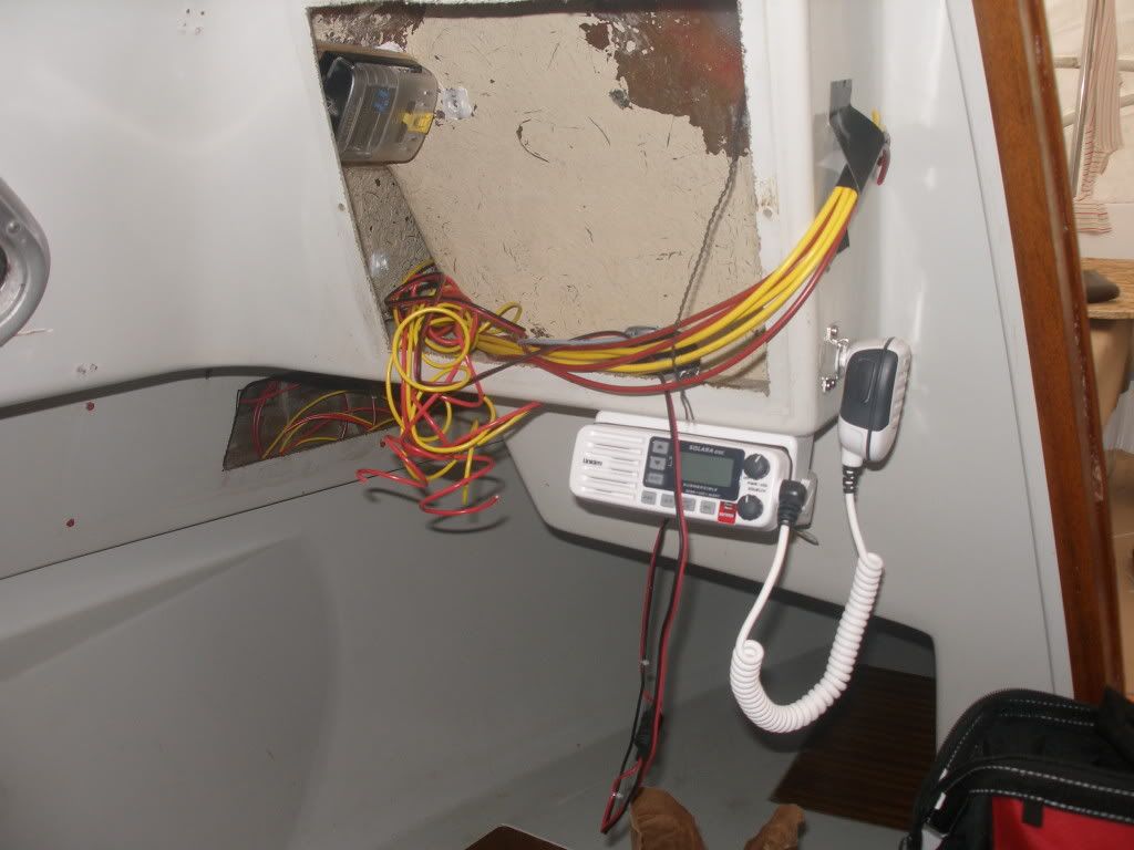
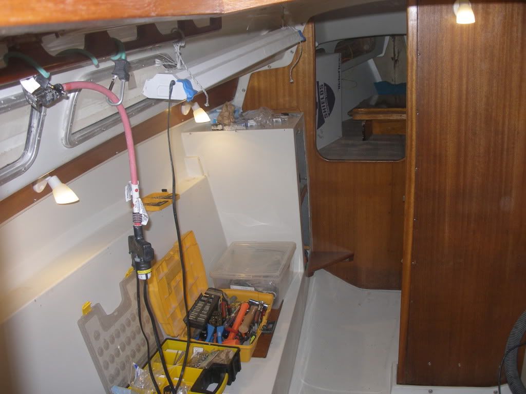
Wiring! Mass of tangled spaghetti it looks like right now. I think I only forgot to label two wires and they are negatives so it may not matter. I haven't finished running wire yet so its not all tacked down and pretty.
Port instrument locker
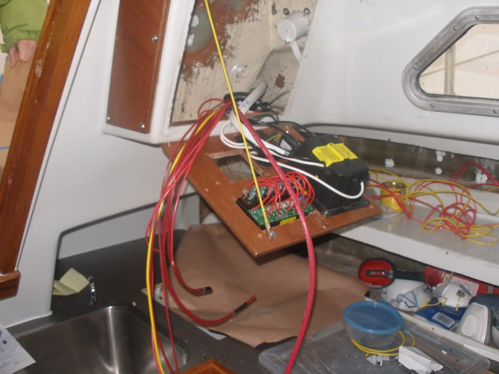
Stbd instrument locker and back of panels. I had to put the AC panel next to the DC, which I originally didn't want to do but it was the best location.
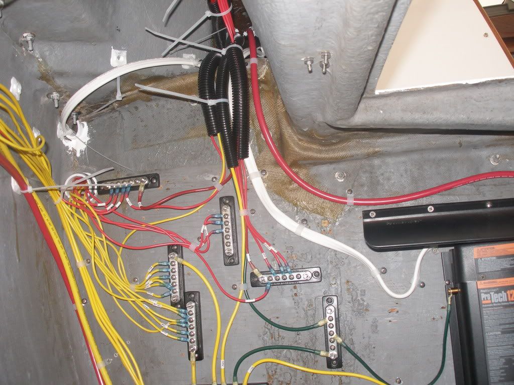
Aft bulkhead wire terminations. I still have some cleanup and the larger sized wiring to do. I've spent a lot of time lying in the lazarette recently!
Re: Ericson 27 Project
Posted: Fri Mar 11, 2011 1:55 am
by bigd14
Things have slowed down a little bit, but I have been doing some work, mostly electrical. Not much worhty of an update until now. I finally got the panels wired up and the stereo and VHF installed. Very tedious since I seem to always be running out of the appropriate fittings and have to stop and go get them. And its just slow work. Next up is to double check my work and then install the light fixtures.
Back fo panel. Kind of a nightmare. I wish I had a slightly larger area for a panel.
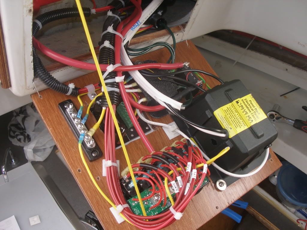
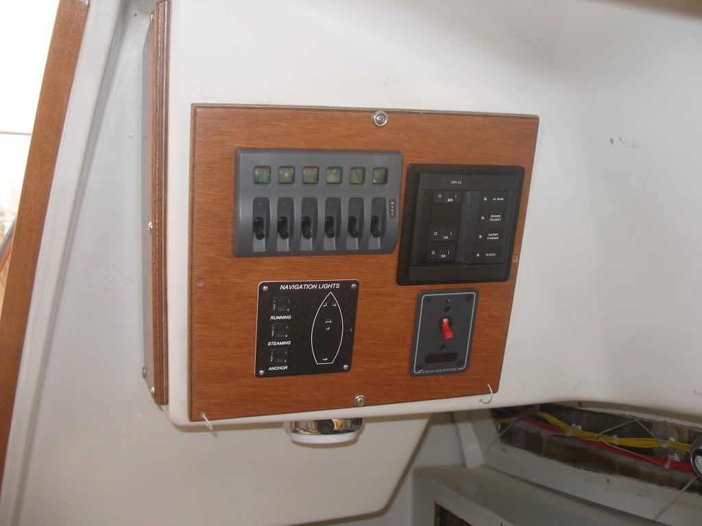
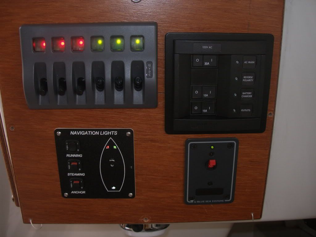
At least the front of the panel looks clean!
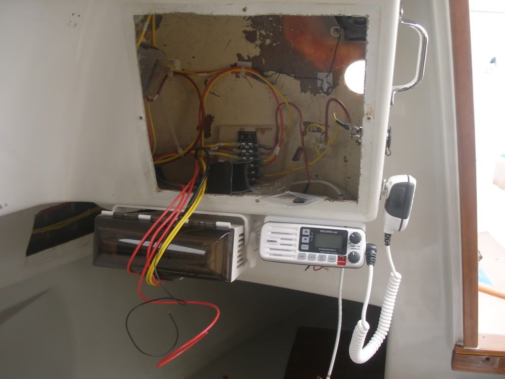
Stereo and VHF and Instrument area.
Re: Ericson 27 Project
Posted: Fri Mar 11, 2011 7:45 pm
by Zach
Looking good!
One tip, to keep some skin on your knuckles... If you take a razor blade and hold it flat to the box side of your zip ties, and pull the tail the same direction you are cutting the tail... It will make a stress riser in the plastic, and cut the tail off below the surface so you can't get cut on the sharp ends.
One of those things a buddy of mine passed on to me a few years ago that I heard trumpets from heaven ring down after his words were spoken... try to share it whenever possible!
Grin.
Zach
Re: Ericson 27 Project
Posted: Sat Mar 12, 2011 12:43 am
by bigd14
Thanks for the tip, Zach! Wish I had known about that a couple days ago... I just finished tightening up my wire runs! Oh well, just makes me that much more cautious working around wire bundles, which maybe is a good thing.
Doug
Re: Ericson 27 Project
Posted: Sat Mar 19, 2011 11:10 pm
by ghostwriter247
just out of curiosity how did you calculate the new spreader length and rigging length to make sure the angles stayed correct when you moved your chainplates outboard?
Re: Ericson 27 Project
Posted: Sat Mar 26, 2011 10:27 am
by bigd14
RE the spreader length: I haven't figured it yet. Ballenger sent them a couple inches longer than the originals to account for this so I can cut them to the right size. There are a couple formulas in Brion Toss's book. One of them is between 40 and 50% of the beam width (that would include both spreaders I think). The other is to measure the distance between the spreader base and the upper attachment of its wire and divide by 5. I need to measure this today.
At any rate, I am going to seek the advice of a professional rigger on this and other matters soon.
Re: Ericson 27 Project
Posted: Sat Mar 26, 2011 12:45 pm
by mitiempo
The upper shroud should be vertical or very close to it from the spreader down to the deck. The angle between the spreader and the shroud should be the same above and below. With longer spreaders there is less load on the rig as the upper is pulling more to the side and less straight down.
Re: Ericson 27 Project
Posted: Sat Mar 26, 2011 6:28 pm
by Paulus
mitiempo wrote:The upper shroud should be vertical or very close to it from the spreader down to the deck. The angle between the spreader and the shroud should be the same above and below. With longer spreaders there is less load on the rig as the upper is pulling more to the side and less straight down.
Interesting - I posted a question to the Mariner board on this just the other day... It seems my fellow Mariner owners have the upper shrouds connected perfectly papallel to the mast, i.e. it sits on the chainplate exactly next to the mast - the (single) lower shroud sits on the next aft chainplate, slightly aft of the mast (by about a foot) - there is no forward lower.
On my boat, when I picked her up in Maine last year, the yard had reversed these two, i.e. the upper was giving the mast some benefit of swept back speaders and uppers connected behind it - I figured that was because the mizzen lacks a permanent backstay.
The boat does have a moveable (running?) backstay (a stainless wire connected to the top of the mast with block-and-tackle attached to the bottom end).
I am about to put the masts back up after I am done varnishing them and wondered what the proper set-up is. The schematics for the boat also show the mizzen uppers perfectly parallel with the mast...

I guess that's where they should be?
Re: Ericson 27 Project
Posted: Sat Mar 26, 2011 6:37 pm
by mitiempo
Yes, parallel to the mast.
Your runner connects to the top of the mast? Runners should be connected at the same point as the inner forestay, assuming a staysail will be flown from it. They counteract the forward pull of the staysail and prevent mast pumping is heavier winds. The backstay supports the top of the mast and no additional stays should be needed at the very top.
Re: Ericson 27 Project
Posted: Sat Mar 26, 2011 6:43 pm
by Paulus
My inner foresaty is the "triatic" I believe it is called (on a schooner at least)...
See edit - added schematic - above.
I will have to double check to see what connections there are on the top. I just took the tarp off and can take pictures...
Thanks for the comeback...
Re: Ericson 27 Project
Posted: Sat Mar 26, 2011 7:13 pm
by mitiempo
Paulus
The uppers should be on the middle chainplate, the lowers on the chainplates fore and aft. The yard got it wrong.
A triatic stay is the one connecting your main masthead to the mizzen masthead. If the mizzen boom is inboard of the transom this often continues down to the transom or a boomkin if one is fitted in lieu of a main backstay. I see you have what looks like twin backstays for the main mast. The triatic doesn't do much as drawn except keep the top of the mizzen from bending aft. I also see you do not have a staysail stay for a smaller foresail so runners are not necessary.
Great looking boat.
Re: Ericson 27 Project
Posted: Sun Mar 27, 2011 5:19 pm
by Brodie
I think there might be two different discussions going on here about the angle of the cap shrouds... just moving the chainplates straight outboard won't (or shouldn't!) change the sweep angle on the spreaders, but will change the angle of the shroud athwartships between the chainplate and the spreader end. I think this is what ghostwriter was referring to. FWIW, during my time in the Landing School's yacht design program, the "rule of thumb" for that angle was 1 degree (ie the shrouds angle inboard with height). This was an aesthetic device - if the shroud exactly parallels the mast all the way to the spreader visually it will appear as though the spreader is wider than the shroud base. The 1 degree angle will make the shroud "appear" as though it is parallel. (there are lots of similar tricks like this - for example, cabin sides that appear "vertical" as on an older wooden boat are actually angled in by 1/4" for every foot of height, otherwise they will look as though they are slanted outboard). As far as keeping the rig up the angle doesn't matter that much unless it gets extreme one way or the other. The S boats in Newport have shrouds that angle outwards as they go up to the spreader, and most of the older Island Packets have an inboard angle much more than 1 degree...
Re: Ericson 27 Project
Posted: Sun Mar 27, 2011 5:23 pm
by mitiempo
I agree, a slight inward angle will look better. Longer spreaders will lessen the load on the rig, possibly at the expense of windward ability due the the wider sheeting angles, but the trade off can make sense for some.
Re: Ericson 27 Project
Posted: Mon Mar 28, 2011 12:41 am
by bigd14
Let there be light!
And there was... After 5 months of learning, research, acquisition and implementation!
Re: Ericson 27 Project
Posted: Mon Mar 28, 2011 1:25 am
by Rachel
Don't you think that fluorescent tube fixture might bang around in a seaway?
Seriously though: Congrats! Figuring out exactly how to wire a boat project from scratch is something I have never done, and it seems intimidating. Yay you for tackling the learning curve :)
Rachel
Re: Ericson 27 Project
Posted: Mon Mar 28, 2011 8:29 am
by Chris Campbell
Congrats!
Looks great, and I know how satisfying it is to turn it on and have it work after all that work. Enjoy!
Re: Ericson 27 Project
Posted: Mon Mar 28, 2011 11:53 pm
by ghostwriter247
congrats on the electrics! Hope mine go as well.
With the spreader length yes i was referring to length the spreaders to maintain the angles being the same. I was under the impression it was a mandatory when moving the chainplates outboard. Did you say the opposing angels must simply be close then?
Being inland Im not even sure we have a professional rigger here, though with the marina opening I'm sure somebody will know.
Since your chainplates seem to be non standard with the four bolts in a square instead of a long strap type how did you work out the loads? Seems like a better, more compact design, I might have to borrow it!
Seems like if i just recreated your design and measurements, it would hold on my bristol as well given we have similar size boats and sail plans
Josh
Re: Ericson 27 Project
Posted: Tue Mar 29, 2011 12:31 am
by bigd14
Rachel wrote:Don't you think that fluorescent tube fixture might bang around in a seaway?Rachel
Funny, that thing has become such a permanent fixture I didn't even notice it in the photo until you mentioned it!
Josh, the chainplates attach to the remnants of the old chainplates still embedded in the hull. Check earlier in this thread for details.
Doug
Re: Ericson 27 Project
Posted: Fri Apr 01, 2011 10:34 pm
by bigd14
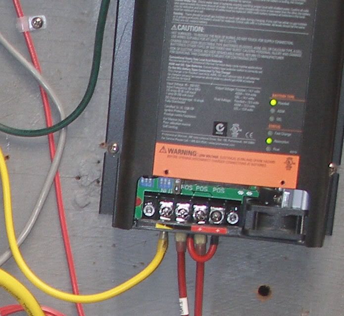
So today I finished up the electrical project with the installation of a Victron battery monitor. With some trepidation, I powered up the AC side for the first time. Unfortunately the red light indicating reverse polarity came on. After a moment of panic I figured I would try another receptacle (I was plugged into a standard GFCI outlet with an adaptor). Luckily the indicator turned green. Whew! Now I need to test the oulets to see if they are the problem or my installation is!
Anyway, it all went well except for the battery charger...
The ProMariner ProTech1210i battery charger does not seem to be supplying a charge to both batteries. I connected it to both banks, jumpered the third output to the second one as per the manual, and fired it up. Battery bank two read 14.58 volts, while bank one only read 12.61. I would have expected both banks to charge simultaneously. I measured at the battery terminals and at the output from the charger. I did not leave the charger on for more than half an hour because I had to leave the boat and did not want to leave it unattended with an untried system running.
Is this normal? Would it eventually switch to the other bank when bank 2 was sufficiently charged? I thought it was supposed to do it simultaneously. I wonder if my primary battery bank is too big for this charger? Seems like that wouldn't matter it would just take longer.
I tried to call customer support but by the time I realized I needed to call them it was 5:03 Eastern time... So I will call them on Monday, but I am hoping someone has any insight in the meantime. Oh and yes, I did read through the owners manual, at least three times! And I have sent ProMariner an email.
Doug
Re: Ericson 27 Project
Posted: Fri Apr 01, 2011 11:13 pm
by mitiempo
Doug
Is the negative post of your batteries connected at one point? I just looked at the manual and can't see where else you could have gone wrong as long as the #2 and #3 positives are jumpered.
As far as the reverse polarity, it has to be the dock as the reverse polarity indicator is wired between the incoming neutral and the ground bus. It will only light if the incoming hot and neutral are reversed, in other words if a voltage exists between neutral and ground.
Re: Ericson 27 Project
Posted: Sat Apr 02, 2011 10:19 am
by bigd14
Yes I have a common ground. I am going to reveiw the installation again today, though. And thats comforting to know about the shore power. Thanks!
Re: Ericson 27 Project
Posted: Sun Apr 03, 2011 6:13 pm
by bigd14
Much ado about nothing re the batttery charger. Apparently the model I have is suitable for two battery banks, but it has outputs for three banks. I had simply wired one battery to a post that was not providing a charge. Doh!
Re: Ericson 27 Project
Posted: Sun Apr 03, 2011 6:51 pm
by mitiempo
Strange - if the third connection was jumpered to the second they would both have been positive outputs.
Re: Ericson 27 Project
Posted: Wed Apr 06, 2011 1:07 am
by bigd14
Apparently I was too busy reading the manual to notice the markings on the charger indicating where the positive leads should go...For some stupid reason I did not notice them even when fiddling around staring right at them.
Re: Ericson 27 Project
Posted: Fri May 06, 2011 11:02 am
by bigd14
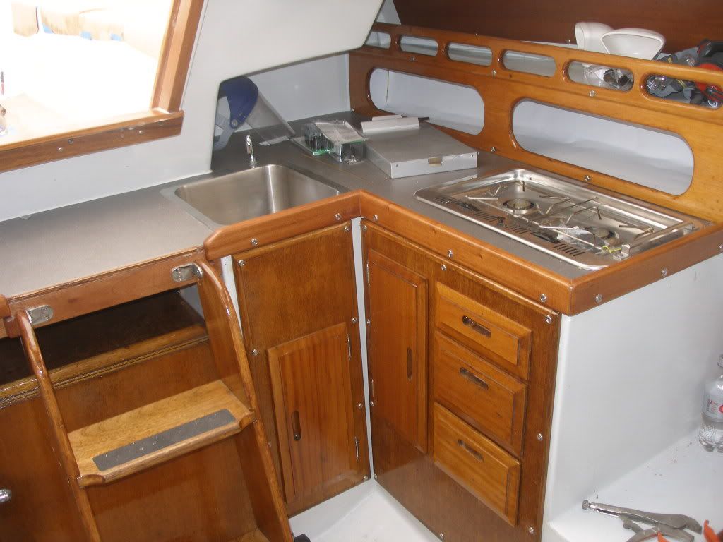
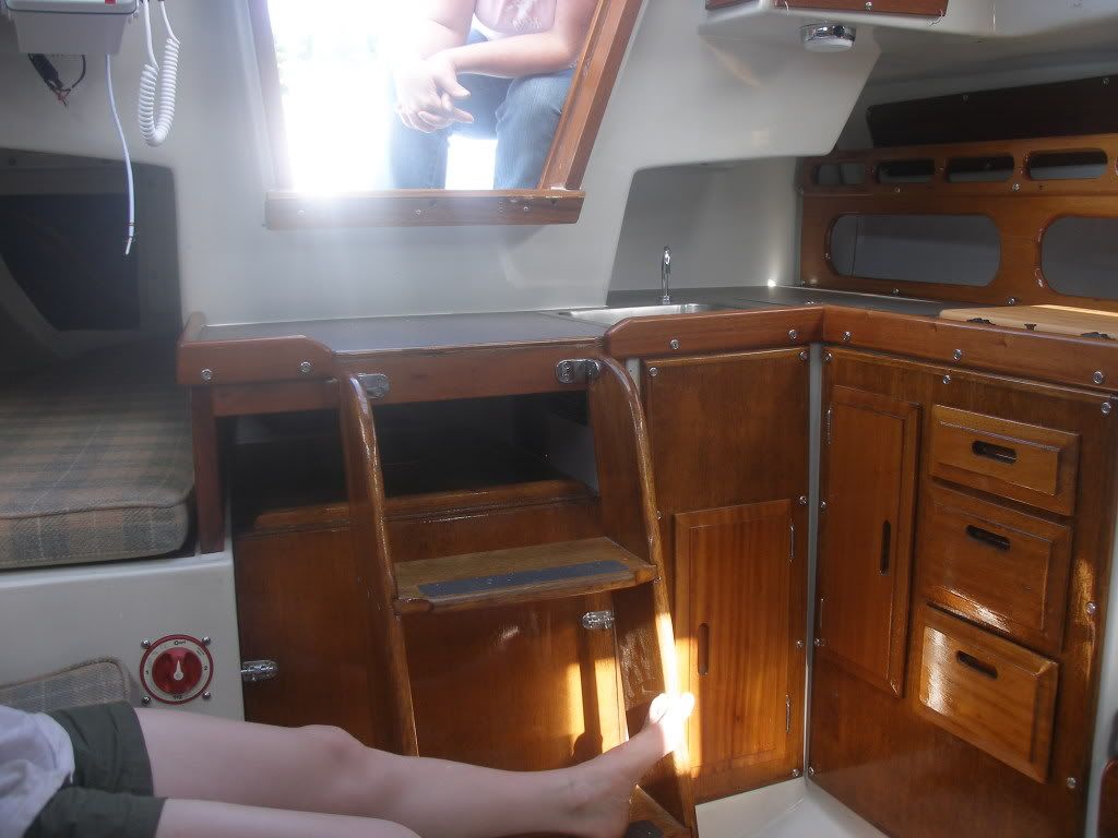
I finally found my camera! I have spent the last month mostly finishing up the interior. Almost all the woodwork is back in, the electrical system is complete, and the water system is installed except for the vent line.
Galley area woodwork
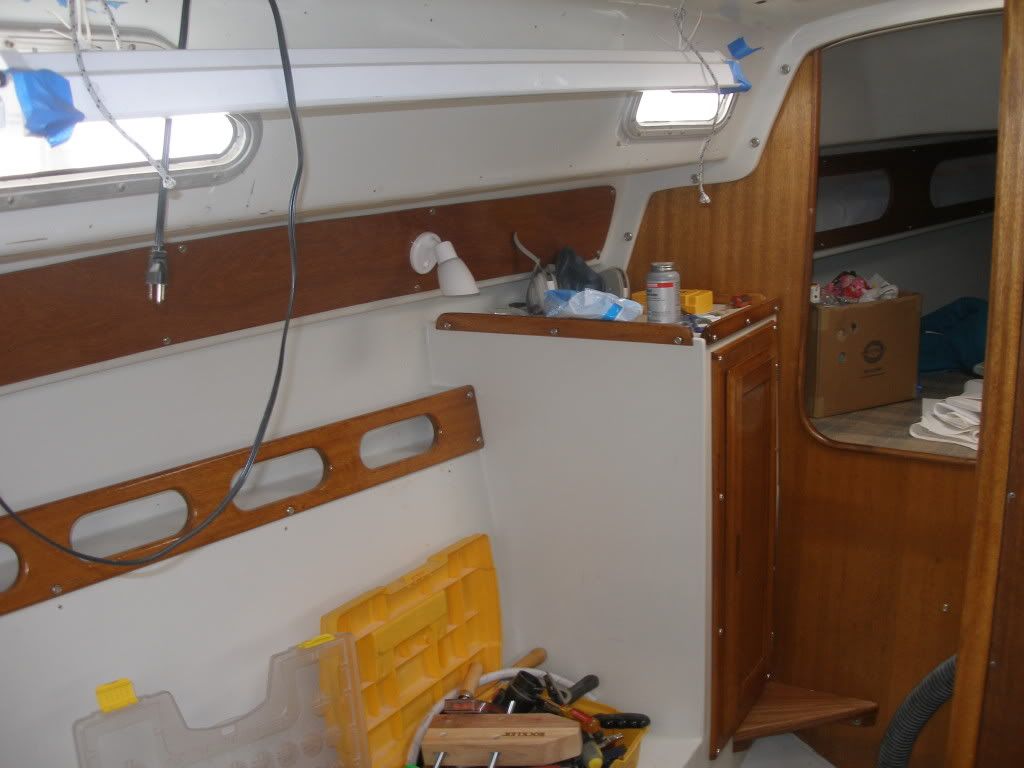
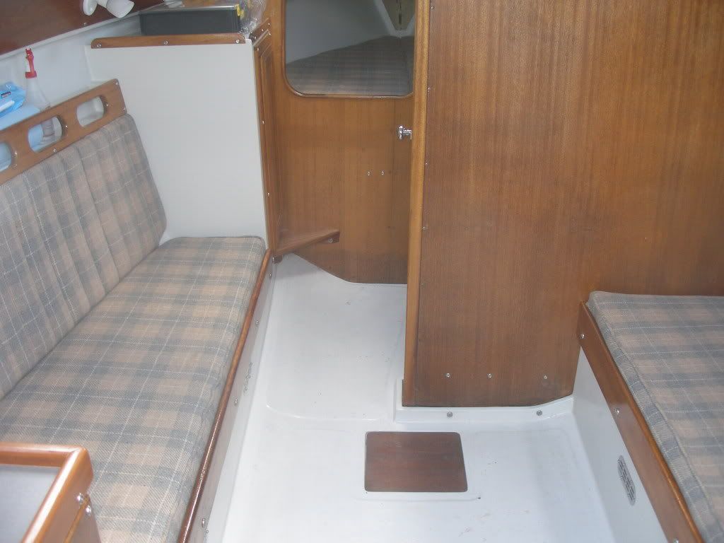
Looking forward (yes, my ugly worklight is still there!)
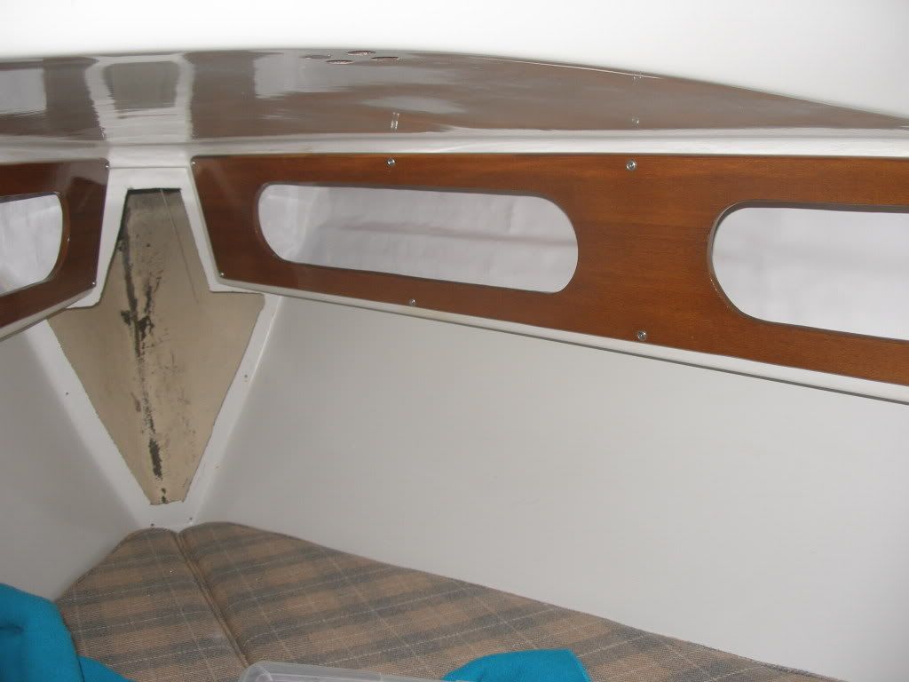
V-berth. We opted to replace the vinyl cubby backer in kind. It was too difficult to remove the old contact cement and fair and paint, which would have been my preference. There is not much room to work a tool in there. We used Liquid Nails instead of contact cement, so the vinyl wouldn't bond to itself or stick where it wasn't wanted. It was still a messy uncomfortable job.
Re: Ericson 27 Project
Posted: Fri May 06, 2011 11:15 am
by bigd14
I also started work on the mast. I had a rigger survey the mast and associated systems. Turns out my pin sizing on all chainplates and mast tangs was too small and the forestay and upper shrouds were too small as well. Standing rigging will be 3/16 wire for backstay and lower shrouds and 7/32 for the forestay and upper shrouds. My new chainplates will need to be drilled out from 5/16 to 3/8 pins. I am having new mast tangs constructed with 3/8 pins. And I had to drop the masthead off at a machine shop so they could enlarge the existing holes but keep enough meat on the front end. More $$!
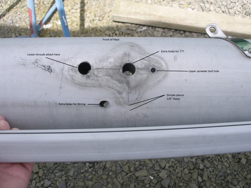
I started work on the spreader bracket repair/replacement. The mast looked like this before the repairs started:
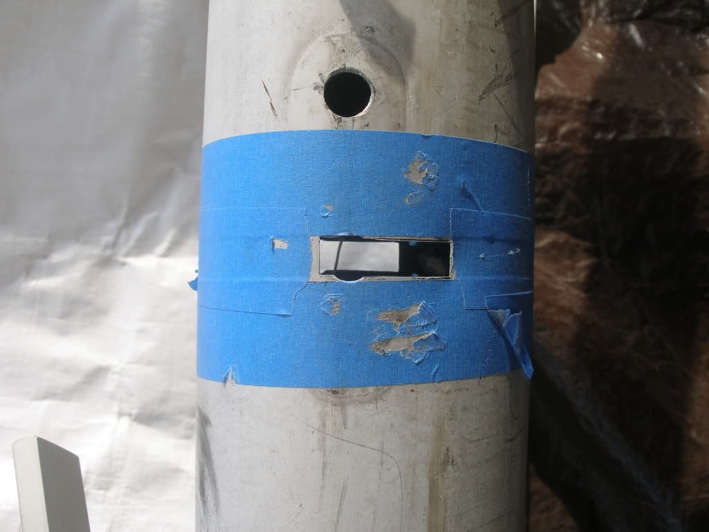
I took the plunge and cut out a rectangular opening for the spreader bar with a jigsaw, then filed to fit. Not shown here but I rounded the corners to prevent cracks.
Spreader bar in place
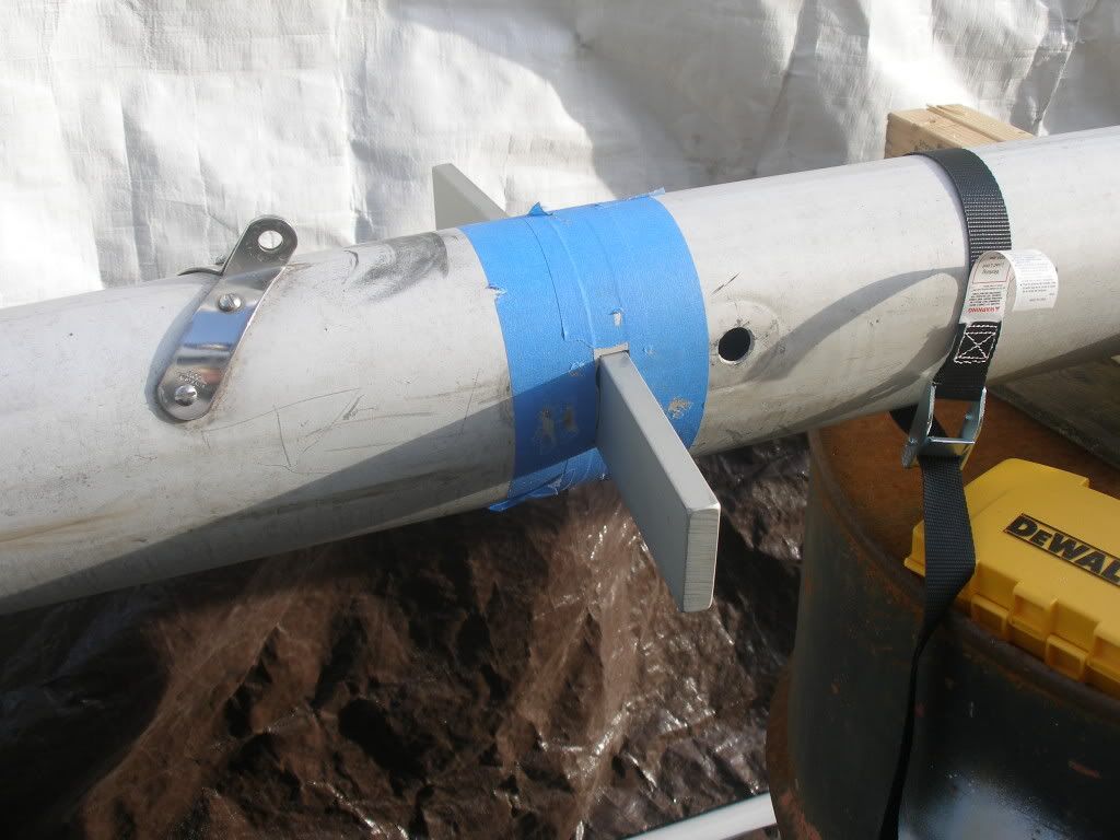
And the repair plates dry fit
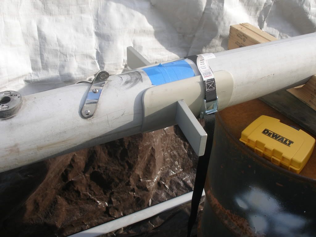
I still need to mark and drill the hole for the lower mast tang and through bolt and then drill and tap the plates into place.
Re: Ericson 27 Project
Posted: Sun May 08, 2011 1:44 pm
by Mark F
Hi Doug,
Progress looks great. The mast spreader modification is very nice! I need to address that area on my Ericson 27 one of theses days. You must be getting close to launching!?
Re: Ericson 27 Project
Posted: Mon May 09, 2011 1:08 am
by bigd14
Hey Mark- Hoping to launch in the next couple months! Lots of mast work and then paint the bottom and it'll be ready to launch. Lots of additional work after that, but it will wait until next winter.
Doug
Re: Ericson 27 Project
Posted: Mon May 09, 2011 8:43 am
by Chris Campbell
bigd14 wrote:Hoping to launch in the next couple months!
Congratulations! You've worked long and hard on that boat, I really look forward to seeing her in the water, and hearing you tell us all how wonderfully she sails!
Re: Ericson 27 Project
Posted: Sun May 15, 2011 11:25 pm
by bigd14
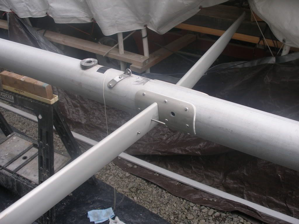
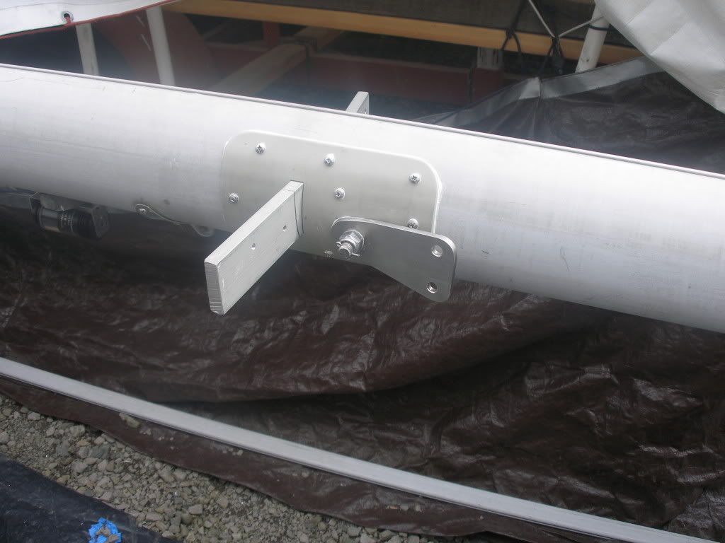
We spent most of the weekend working on the spreaders and repair plates. Quite a finicky process to get it all to fit correctly. The spreader bar is still a tiny bit loose in the mast, I just could not get it to tighten up fully. Guess we'll have to live with it. We also applied the last round of barrier coat to the patches on the hull.
Plates and spreader bar in place using #10 screws and 5200. This took a lot of filing to get as tight a fit as I could.
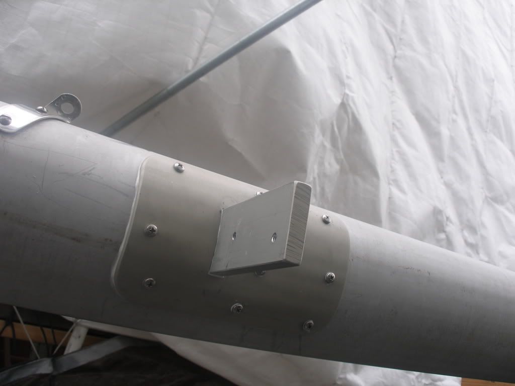
Spreaders temporarily in place. It took forever to get them to match the mast radius (thats ink, not a gap!)
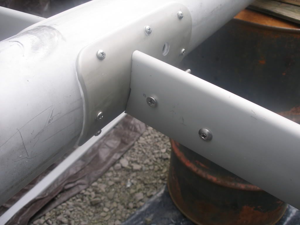
Spreaders temporily in place.
Re: Ericson 27 Project
Posted: Mon May 16, 2011 3:30 am
by Skipper599
I hate to raise a bogeyman at this late stage in your project Doug, but I've only just now viewed the pics of your spreader bracket.
When it comes to cutting holes in mast sections, sharp 90 degree corners are a definite NO NO. They will create a natural stress riser at each of those points and will lead to early failure.
Even at this late stage Doug, you can take steps to prevent such a disaster by filing or grinding all eight corners of the two rectangular openings in the mast section itself.
Using a 1/8" or 3/16" dia fine tool - either a file or a small grinding tool - you need to create very gentle smooth radiused notches. Leave no sharp corners or cut marks.
If you can visualise using the very corner itself as the centre point for a drill, you will end up with what would look like a "bubble" at each corner if drawn on paper.
It might look a little strange but your additional cover plates (screwed on) will hide them from view.
I hope you understand what I am attempting to describe to you. Sorry I don't know how to draw sketches on the computer.
Re: Ericson 27 Project
Posted: Mon May 16, 2011 11:12 am
by Mark F
Hi Bob,
Doug wrote that he did round the corners, just didn't take a photo. Looks great Doug.
Re: Ericson 27 Project
Posted: Mon May 16, 2011 11:44 am
by Skipper599
Ok, thanks Mark, I didn,t see that anywhere or maybe I just didn't read ALL of his posts.
Re: Ericson 27 Project
Posted: Mon May 16, 2011 3:21 pm
by bigd14
Yep I rounded the corners with a small round file but only on the mast not the repair plates. The repair plates are very thick and I wanted a snug fit so I decided to leave them square. But thanks for bringing it up, that's something I would want to address.
Doug
Re: Ericson 27 Project
Posted: Tue May 17, 2011 6:10 pm
by ILikeRust
Jeez, and here I thought I was doing a lot of work on my boat.
I have to do some of the same things you've done, but I'm not going to do them all at once. A little here, a little there, over the next few years...
Looking good!
Re: Ericson 27 Project
Posted: Fri Jun 03, 2011 2:45 pm
by bhacurly
Looks great Doug!
I looked back an maybe I missed it,,, but I was wondering where you got your spreader bar and plates from???
Geeze I looked back to 2009!!
Billy
Re: Ericson 27 Project
Posted: Fri Jun 03, 2011 4:57 pm
by Skipper599
Hello bigd14, can you tell me what is the model # or part # for the 120v AC Sw. shown in one of the pics posted Mar27/2011
It's shown to the right of the 12v Sw panel with the red & green lights.???
Also, is this a GFCI type sw unit??? or, do you rely on land power outlet GFCI for protection???
Actually, I would be interested in knowing what all your components are because it would suit my needs perfectly.
Thanks . . . . Bob T.
Re: Ericson 27 Project
Posted: Sat Jun 04, 2011 12:05 am
by mitiempo
Bob
I think it is a DC main switch. The AC panel above it (360 series from Blue Seas) has the double breaker 30 amp main AC breaker at the top.
Never rely on any GFCI off the boat for safety. In a circuit of outlets the first should be a GFCI. It will protect the others downstream.
Re: Ericson 27 Project
Posted: Sat Jun 04, 2011 4:14 pm
by Mark F
Hi Billy,
Doug must be working on the boat ;-). He had Ballenger Spars
http://www.ballengerspars.com/ make the spreaders and plates.
Re: Ericson 27 Project
Posted: Sat Jun 04, 2011 9:14 pm
by bigd14
Mark is correct! I have been working on the boat after a couple weeks off due to a bad reaction to some medication I was taking, Ugh.
Billy, yes Mark is right, it was Ballengers. They made a really quality product for me.
Bob- Mitiempo is correct, that is the DC main panel switch. That way the panel can be switched off for maintenance but the motor can still be powered up. The AC comes into the Blue Sea panel on the upper right in the photo. I have two AC breakers, one that goes to the battery charger and one that goes to a single GFCI outlet. Here is the final electrical schematic:
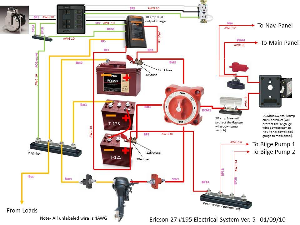
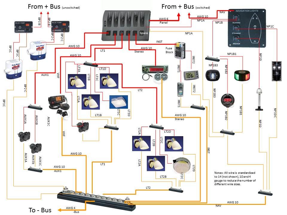
Sources: I used Blue Sea as much as possible.
http://www.genuinedealz.com for wire and end fittings, my local chandlery and West Marine for the stuff I forgot (alot!) and
http://www.sailorsams.com for the interior lights, and Jamestown Distributors for some of the nav lights.
Re: Ericson 27 Project
Posted: Sat Jun 04, 2011 9:22 pm
by mitiempo
Doug
Looks like a very well thought out system. At a quick look I see nothing wrong with it. You oversized some wires in my opinion but other than their expense that is fine.
Normal AC wiring is 14 awg which will more than carry the max output of the breaker (15 amps)
The 10 awg you have used for items like the stereo are huge overkill as well. Most stereos use way less than 5 amps.
Looks to be a trouble free system though and you know every part of it - always a good thing.
Re: Ericson 27 Project
Posted: Sat Jun 04, 2011 9:28 pm
by bigd14
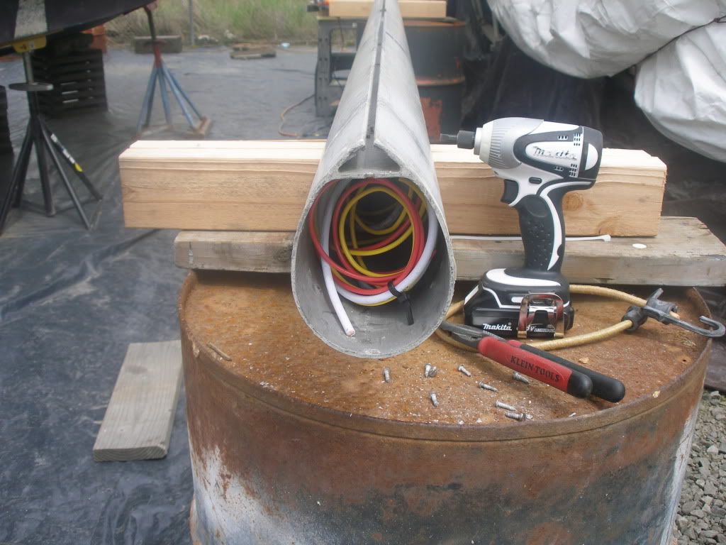
Here is the latest progress:
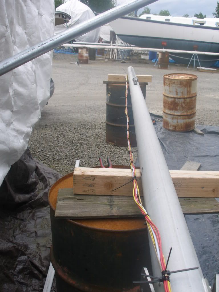
Wiring in the mast- I did the zip tie spider trick every couple feet.
Lower shroud tangs
Upper shroud tangs and masthead
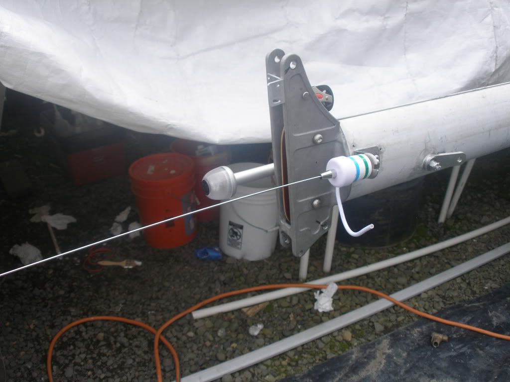
Topping lift block and shims
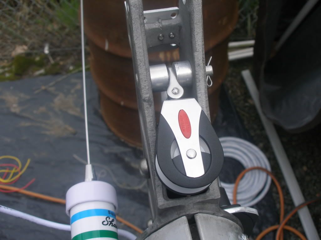
Mast wiring at base (and the Best Tool Ever)
Re: Ericson 27 Project
Posted: Sat Jun 04, 2011 9:43 pm
by bigd14
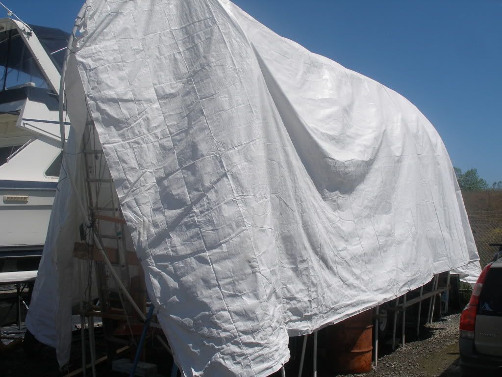
And some more progress this weekend! After a spring where the temperature rarely got out of the 50's it hit 92 today. Kind of a shock to the system since last week I was working in fleece and a raincoat!
Shelter coming down
New primary winches (found out the old ones were pretty worn and were not good for everyday use, but I left them on because they were in the wrong place for a fair lead to the jib track, for use as a handhold, and for an anchor point for various items, and because I didn't want to patch the holes!
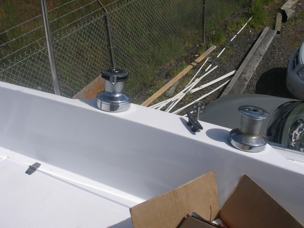
Wow I can actually see more than 20 feet in front of me now!
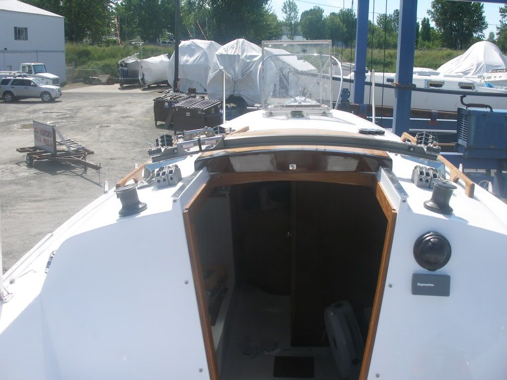
Bow pulpit is on now that the cover has been removed
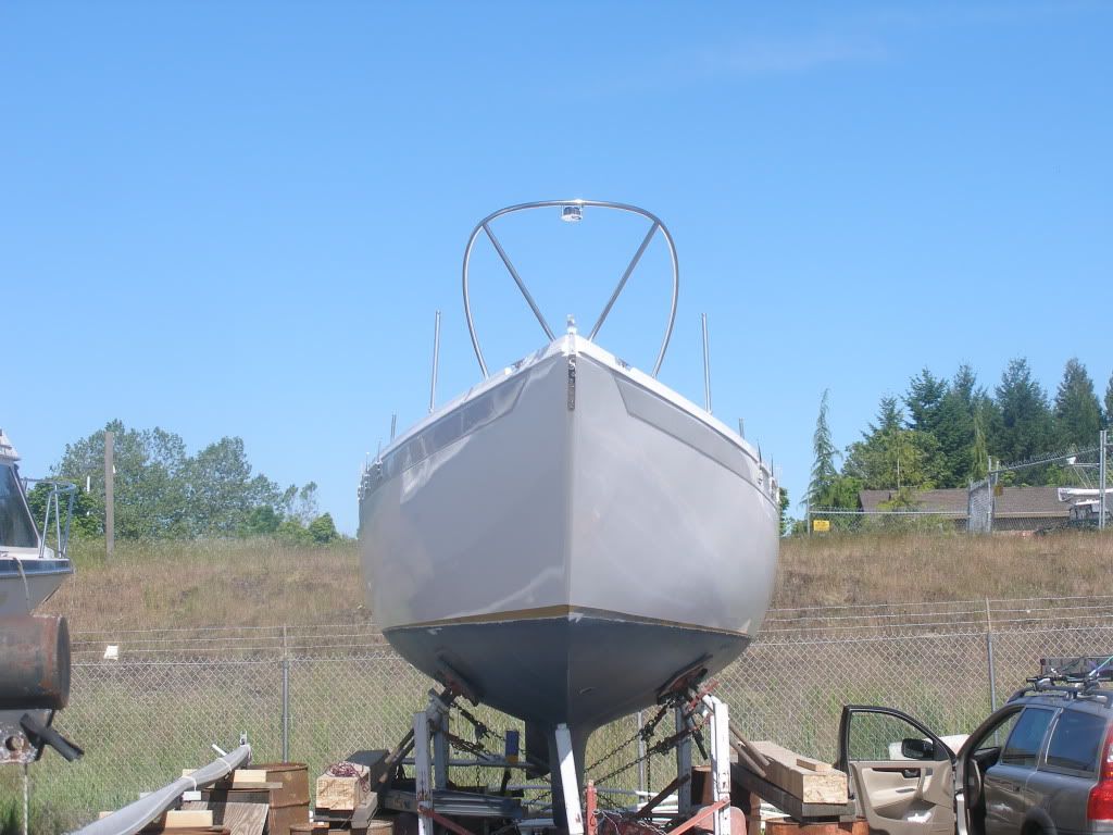
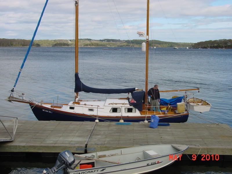
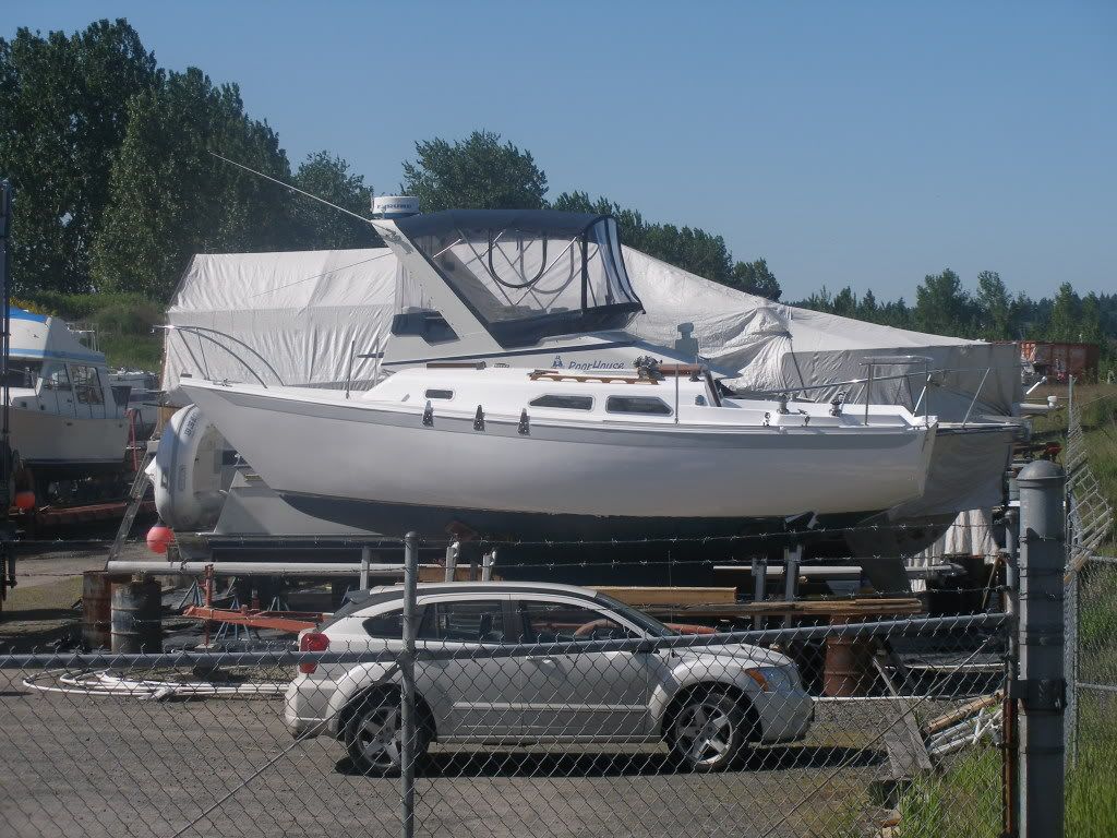
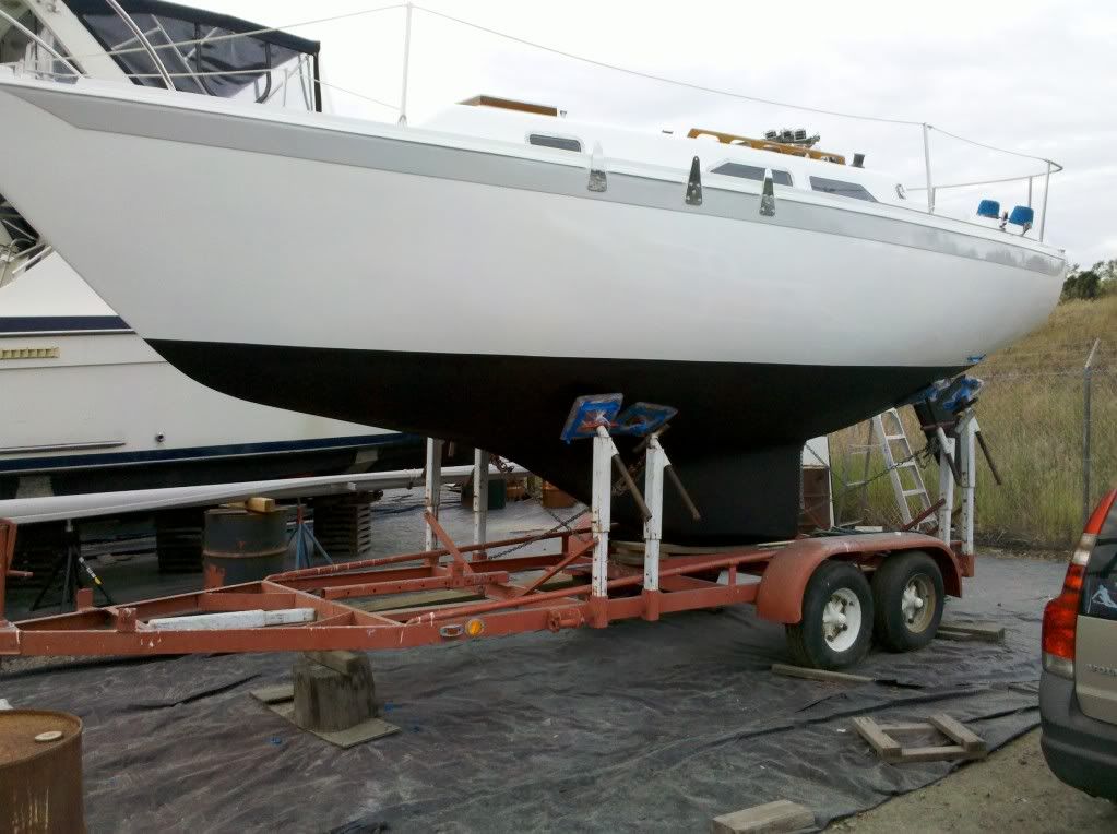
Its a 20 foot boat. Get too close and the imperfections start to appear! But she looks good from a distance.
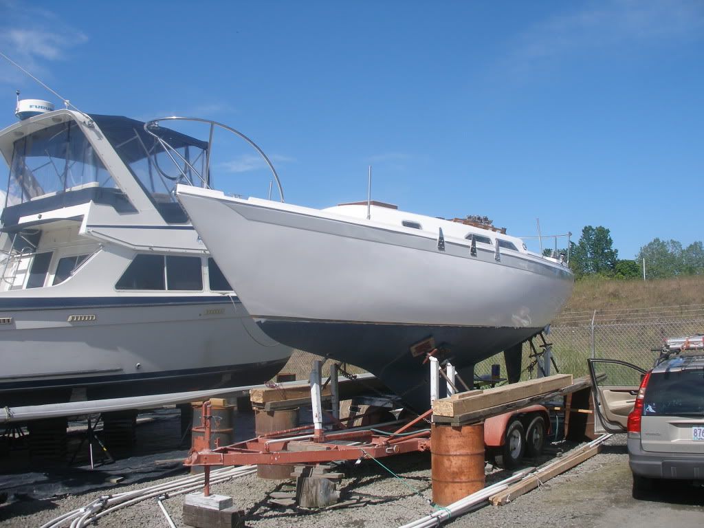
Side view
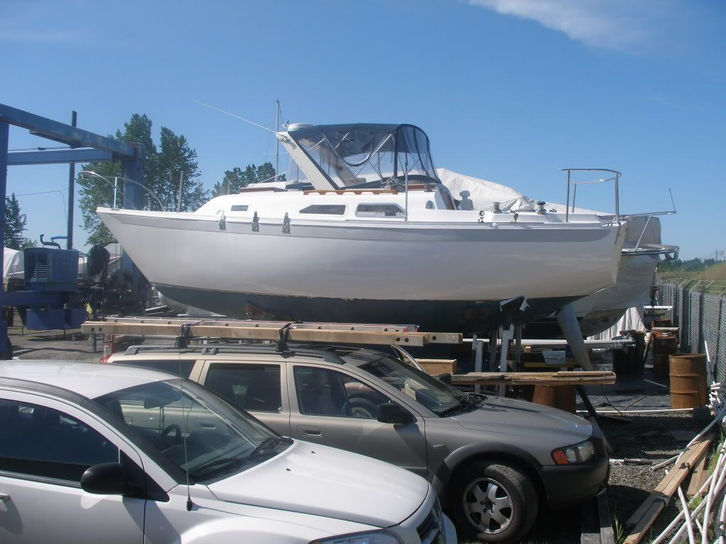
My kids think the boat looks really small... Since we spent two and a half years working on it, I think I should have got a bigger boat! And I think I messed the waterline up pretty bad. There was no way in the small shelter I could get a good look at it to eyeball it. Oh well.
Re: Ericson 27 Project
Posted: Sat Jun 04, 2011 9:48 pm
by mitiempo
Looks great.
Re: Ericson 27 Project
Posted: Sun Jun 05, 2011 1:01 pm
by Mark F
Hi Doug,
She looks great. I think your waterline will be fine. I compared your photo with a photo of my Ericson 27 in the water and they are pretty close. As she sits on the hard the bow is high. I hate to bring it up but I think you put the dodger on backwards ;-).
Re: Ericson 27 Project
Posted: Mon Jun 27, 2011 12:22 am
by bigd14
More progress. Things are getting very close!
Interior is mostly back together:
Original cushions. A bit tired, but will do for now.
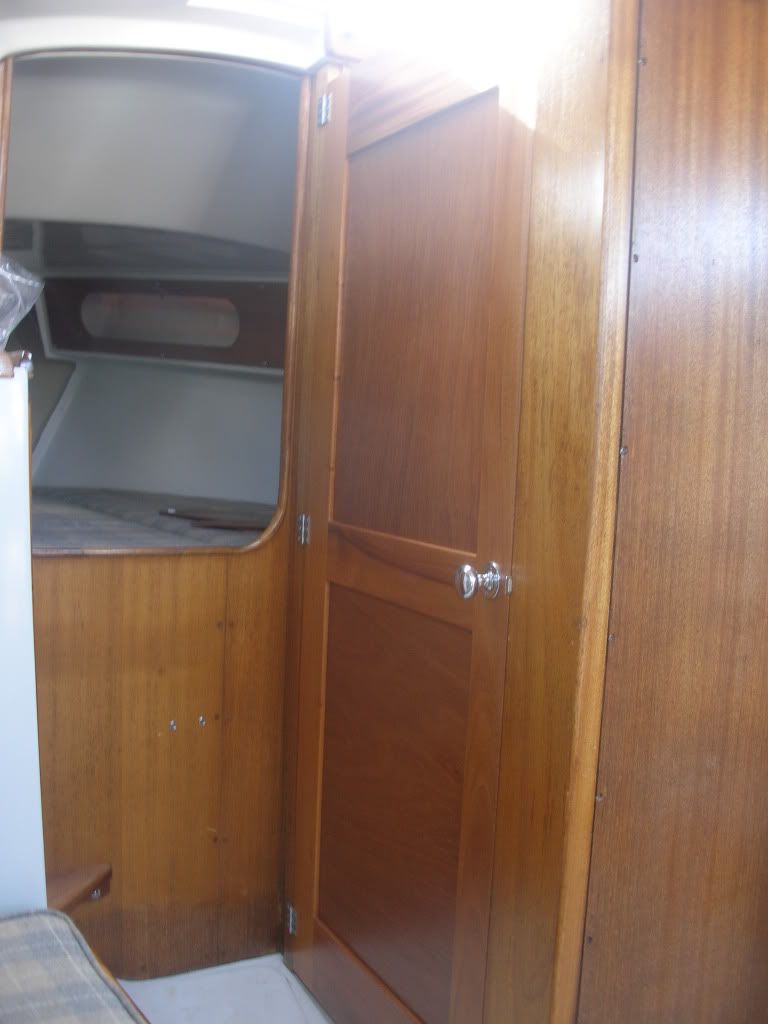
The new head door built over the winter
And I got the bottom paint done today!
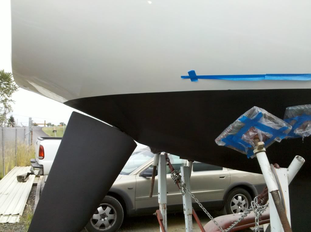
Just a little bit more work on the mast and rigging and she'll be ready to go back in the water.
Re: Ericson 27 Project
Posted: Mon Jun 27, 2011 11:46 am
by Mark F
Hi Doug,
Looks great. I really like how the galley modification turned out. Are you leaving the rubrail off? The boat looks clean without it.
Re: Ericson 27 Project
Posted: Tue Jun 28, 2011 1:49 am
by bigd14
Hey Mark- Thanks! Yep I am going to leave the rubrail off. If I had another year or so, I would have ground it down and glassed over it. But I had to draw the line somewhere on sanding and grinding! I am really happy with how the galley mod turned out. I gained a ton of counter space and it makes a really great first step.
Halyards and other running rigging arrived today. I figured I would color code them a little bit to help my kids and guests figure out what was what- white with red flecks for jib controls, and white with blue flecks for mainsail controls (and then blue with white for mainsheet and traveller). Unfortunately they look kind of silly. I should have just gone with all one color. Oh well. It will only be 10-15 years that I have to live with it...
With all the rigging at hand I am ready to rig the mast and launch. Hopefully the river will continue to go down. The travelift sits on a channel where the current is blasting through at 4-5 knots right now and I have to travel through a narrow slot between docks perpendicular to the flow to get out to it (the downstream docks are creating bow waves!). Not something I really want to face right off the bat with an untested motor and not knowing how the boat handles. I may wait a couple weeks until things slow down a little!
Doug
Re: Ericson 27 Project
Posted: Wed Jun 29, 2011 7:11 pm
by JoeC
These comments are not intended to pour cold water on your impressive project but felt obligated to pass on some issues I noticed about the reinforment detail on the mast at the spreader bar.
The size and thickeness of the added reinforcing plate looks ok.
For future reference..cutting a horizontal slot in the mast is usually not a good idea. It removes alot of material in an area of the cross section of the mast where, in this case , it is needed the most. Even with rounded corners, it could lead to a horiz crack in the section. This area also has a concentrated load from the spreader which does not help the situation.
The biggest immediate issue is the use of #10 screws in attaching the reinforcing plate to the mast.
To me they look way undersized.......you could try and track down the shear capacity of this screw if you know the type of stainless steel that it is made out off.
There are only 3 screws that are effective in making the reinforcing plate effective in the weak axis bending of the mast.
I don't know , off-hand , what the allowable shear capacity of the screw is, but let's say it is 100lbs/screw.
That gives 300lbs capacity for the reinforcing plate for weak axis bending of the mast.
If there is a gap between the plate and the mast , this could reduce the shear capacity of the screw significantly.
You may already have addressed this or checked out that the screws are ok for the potential loads.
There are many others on this forum that can offer experienced and knowledgeable comments on this subject.......either way, get a second opinion.
Good luck
Joe
Re: Ericson 27 Project
Posted: Wed Jun 29, 2011 7:56 pm
by TampaBay
The boat looks fantastic. The interior is better than new.
The mast looks like a professional's work: Nine fasteners per side, bedded in 5200, the through bar,,,,,,
Just to comment on JoeC's observation: The strength of that design is easily, many multiples stronger.